|
If you are unable to display correctly math fonts in Netscape under
X11, click here.
|
|
Copyright 2001 IEEE. Published in the Proceedings of 2001 IEEE International Symposium on Circuits and Systems (ISCAS),
Vol. IV, pages 350-353, Sidney, Australia, May 6-9, 2001.
FPGA Realization of RNS to Binary Signed Conversion Architecture
Marco Re, Alberto Nannarelli, Gian Carlo Cardarilli and Roberto Lojacono
Department of Electrical Engineering
University of Rome "Tor Vergata" - Italy
http://dspvlsi.uniroma2.it/
Abstract
The use of the Residue Number System (RNS) in modern
telecommunication and multimedia applications is becoming
more and more important because it allows
interesting advantages in terms of precision, power
consumption and speed. Generally, the output conversion
from residue to binary is the crucial point in effective
realizations of application specific architectures based on
residual arithmetic. This paper presents a general
conversion procedure based on a N moduli set. The
algorithm can process both unsigned and signed
numbers. Based on this algorithm an architecture which
efficiently implements the output conversion is
illustrated. The architecture has been mapped on a
FPGA.
1 Introduction
The advantages of Residue Number System (RNS)
processing are discussed in several publications and books
[5], [13], [14]. Error free
computation, simplified and fast addition and
multiplication, possibility to obtain parallel
architectures are among the more important advantages. New
important RNS research topics, as for example those related
to low power DSP implementations, are also emerging
[1], [2], [11]. The
practical use of RNS is however strongly limited by the
input and output conversions required for the translation
from the binary to the RNS representation and vice versa.
In fact, the implementation of the converters constitutes a
fixed overhead on the total area, delay and power
dissipation. For these reasons the output conversion, which
is generally performed using the Chinese Remainder Theorem
(CRT in the following), still appears to be a crucial point
in the realization of competitive RNS subsystems and,
therefore, represents one of the main topics in the recent
RNS research activities. Some authors have proposed the use
of three moduli sets [3], [4],
[6], [7], [8]
in order to obtain simpler and more efficient output
conversion architectures. For example papers
[7] and [8] consider the set
(2n-1, 2n, 2n+1). Of course, this approach reduces the
exploitation of the RNS properties (the maximum advantages
are obtained by using a lot of small value moduli). In
fact, n grows with the desidered wordlength and,
correspondly, the resulting modular processor becomes
slower. On the other hand, high speed and low power
multimedia applications require DSP hardware with large
dynamic range and fine granularity in the wordlength
selection (this aspect is related to the wordlength
optimization). Of course these requirements cannot be fully
matched by using three moduli. To overcome these problems,
in a lot of applications moduli sets with more than three
moduli are required. In [12] an efficient method for
the RNS-Binary conversion, based on a set of N moduli,
has been proposed. Although this method does not limit the
number of moduli, it imposes an important limitation
because only odd moduli can be used. This reduces the RNS
advantages because power of two modular arithmetic exhibits
very efficient implementations (for this reason, normally
the greatest modulo is chosen of the form 2h). Our work
is aimed to remove the above limitation preserving the
properties of the method presented in [12]. The
paper is organized as follows. Section 2 describes the
algorithm while in Section 3 the extension for the signed
conversion is given. Section 4 shows an actual
implementation of the proposed algorithm. The VLSI
architecture is presented and the mapping on FPGA XILINX
V1000-6 is discussed. The conclusions are drawn in Section
5.
2 The new conversion algorithm
The classical CRT formulation for a N moduli set is
|
áX ńM = |
|
N
ĺ
i = 1
|
|
^
m
|
i
|
á |
^
m
|
- 1
i
|
· rińmi |
|
M
|
= áH ńM |
| (1) |
Where á ńT is the mod T operator,
M = Ői = 1Nmi,
ri = áX ńmi i Î [1, N],
and the quantities [^m]i-1 represent the
multiplicative inverse of [^m]i, i.e.
When (1) is implemented by a digital circuit two
problems arise. The first one concerns the complexity of
the arithmetic operations involved (a set of modulo
additions and modulo multiplications are required). There
are a number of methods to efficiently implement the
computation of the term H. In [9] look-up tables (LUT) are
used to compute the terms and a tree of carry save adders
implements the summation.
The second problem is related to the computation of the external mod M operation.
This operation is very complex [10] due to the large value
of M in the final mod M operator and to the dynamic range of the term H.
In fact, from (1) we obtain the following bounds
|
0 Ł H = |
N
ĺ
i = 1
|
|
^
m
|
i
|
á |
^
m
|
-1
i
|
· rińmi Ł |
N
ĺ
i = 1
|
|
M
mi
|
· (mi-1) < N ·M |
| (3) |
Equation (3) shows the relation between the range of H and N.
Moreover, the methodologies used for the
modulo computation of specific modulus set (as those based
on moduli close to powers of two) do not appear to be
useful for this modulo operation. Indeed, if we maintain
the generality of the procedure, the final modulo cannot be
constrained. To obtain a more suitable form for the mod M operation, let us consider the number X ·2k being
k a suitable integer quantity. Multiplying both the
members of (1) by 2k we obtain
|
áX ·2k ńM = |
|
N
ĺ
i = 1
|
|
^
m
|
i
|
á |
^
m
|
-1
i
|
· ri ·2k ńmi |
|
M
|
|
| (4) |
The terms of the summation in (4) have the same
dynamic range as given by (3) since the factor 2k appears
inside a mod mi operation. Equation (4) can be
rewritten as
|
X ·2k = |
N
ĺ
i = 1
|
|
^
m
|
i
|
á |
^
m
|
-1
i
|
· ri ·2k ńmi-a·M |
| (5) |
where a comes from the external modulo operation. From (5) we
get
|
X = |
N
ĺ
i = 1
|
|
^
m
|
i
|
á |
^
m
|
-1
i
|
· ri ·2k ńmi-a· M |
2k
|
= |
H-a·M
2k
|
|
| (6) |
Properties of (6) has been exploited in
[12]. Due to the presence of a power of two modulus,
this expression cannot be directly used for the computation
of the output conversion. In the present case,
(5) must be modified by taking into account
that one of the residues, is a power of two (we suppose
mN = 2h). In this case, we have
From (7) it derives that the h
least significant bits of X correspond to the h bits of rN. This means that the
reconstruction of these bits does not require any operation
in the residue to binary conversion process. In this case,
the main task of the converter is the reconstruction of
the remaining most significant bits of X. These bits
correspond to the number e defined as
Starting from this value the converted value X can be obtained by
The e value can be computed by introducing
(6) in (8)
where [M\tilde] = M/2h. Since the definition of the
term H implies that
the first term of the numerator of (10) is
an integer quantity [H\tilde] given by
Using (12), (10) can be
rewritten as
Due to the scaling by the factor 2h, this expression
requires for its computation a reduced dynamic range.
Eq.(13) is similar to (6) and, as we
show later, a simplified method can be used to select the
value a[M\tilde]. In the following, all the
expressions are defined in terms of e,
[H\tilde], [M\tilde].
The most difficult task, in the evaluation of
(13), is the computation of the term a[M\tilde]. To solve this problem, we firstly evaluate
the dynamic range of the term [H\tilde].
Starting from (12) we obtain
consequently, the factor a belongs to the interval
(see Appendix A)
Starting from this result, (13) suggests an
efficient method to find the right value a·[M\tilde] to be subtracted to [H\tilde]. In
fact, in order to obtain integer values of e
(the reconstructed value), the quantity
[H\tilde]-a·[M\tilde] must be a
multiple of the factor 2k. This means that the k least
significant bits of [H\tilde]-a·[M\tilde] must be equal to zero. Starting from this
observation, we can derive that the correct value of the
term a belongs to the subset
|
U = {a Î I: áa· |
~
M
|
ń2k = á |
~
H
|
ń2k} |
| (16) |
Where I is the set of integer numbers. This subset only
depends on the k least significant bits of
[H\tilde]. Unfortunately, using these bits we are
able to select only 2k values of
a·[M\tilde], out of the N+2k+1 possible
values, according with (14). If k is chosen
such that
the values of a·[M\tilde] can be computed starting from the 2k positive values
stored in a very small LUT. In fact, since e must be a positive number, the
quantity [H\tilde]-a·[M\tilde] must be positive. If this does not happen, the obtained value of a Î U
is incorrect. From (14) and (16) the correct value is obtained by subtracting 2k from the
incorrect one.
So, if a˘ is the incorrect value addressed by the LUT and a is
the correct one, e is obtained by
The procedure deriving from (18) can be summarized by the following steps.
- The term a˘·[M\tilde] is read from the LUT addressed by the k least significant bits of [H\tilde].
- The sum [H\tilde]-a·[M\tilde] is computed and the k least significant bits are discarded.
- If the obtained result is negative the quantity [M\tilde] is added.
|
3 Signed Number Conversion
The conversion into a two's complement
representation can be easily performed by using the
following conventions for the RNS representation of signed
numbers. Since M is even, positive
numbers are into the range [0,(M/2)-1] and negative ones
are in [M/2, M-1].
The signed conversion must translate these ranges into the
ranges of the two's complement representation (for m
bits,
the positive numbers are in the range [0, 2m-1-1]
while the negative ones are mapped in the interval
[2m-1, 2m-1]). This translation can be performed by
considering the following procedure. As first step we add,
mod M, the quantity P = M/2. This operation translates the positive numbers into the range
[M/2, M-1], while the negative ones are now in the interval [0, (M/2)-1]. As a
final step, the two's complement value of the output can be
reconstructed through the binary subtraction of the value
M/2 from the final result.
This procedure has been embedded in our algorithm and in
order to reduce the algorithm steps, the final subtraction
has been merged with the conditional subtraction required
for the a correction. Therefore if the reconstructed
value X˘ = e˘·2h+árN+Pń2h is positive we only subtract the value P.
Otherwise, for negative values, the quantity M-P = M/2
is added.
The above algorithm can be summarized in the following
steps
- Compute the quantity [H\tilde] using the
modified residue r˘i = ári+P ńmi.
- Compute the quantities e˘, X˘ = e˘·2h+árN+P ń2h.
- Compute the quantity X. If X˘ is negative the two's complement output result
is obtained as X = X˘+M-P otherwise X = X˘-P
|
3.1 A numerical example
In the following, a numerical example is given. Let us
consider the case of a RNS representation based on the
moduli set,
where r4 = 23 (i.e.
h = 3). The number of moduli is four therefore, from
(17), k = 2. For this set we have
|
|
|
|
^
m
|
i
|
= {280, 168, 120, 105}, |
| | |
| | |
|
|
|
and
H=280 1 2^k (r_1+P)_3-168 2 2^k
(r_2+P)_5+
120 1 2^k
(r_3+P)_7+105 1 2^k
(r_4+P)_8
Consider the value X = -209® RNS:{1, 1, 1, 7}.
|
|
| |
|
~
H
|
= |
1684-4 ·á7+420ń8
8
|
= 209 |
|
|
|
|
The correct a value is 1. Consequently we have
e˘ = 26 and for X˘ we obtain X˘ = 26 ·8+ á7+420 ń8 = 211 > 0.
In this case we have to subtract the term P = 420
obtaining X = 211-420 = -209.
4 The VLSI Architecture
The converter architecture for a generic set of moduli
is sketched in Fig. 1. The N LUTs are addressed by the
residues ri and store the terms
|
|
^
m
|
i
|
á |
^
m
|
-1
i
|
·2k ·(ri+P)ńmi |
|
The LUT-N stores the term [^m]Ná[^m]N-12k(rN+P)ńmN-2kárN+Pń2h.
A Carry-Save Adder (CSA) is used to compute
[H\tilde].
The k least significant bits of [H\tilde] are used to
address the LUT a[M\tilde] that stores the multiples a˘[M\tilde].
The selected multiple is added to [H\tilde] in
order to obtain the value e˘. The h least
significant bits of the value árn+Pń2h are directly
juxtaposed with e˘ to obtain the value X˘.
The correct signed value X is obtained by a final
summation. Depending on Sgn(X˘) the value -P or M-P
is conditionally added to X˘.
A VLSI implementation based on the moduli set {3, 5, 7, 11, 17, 64} for a 20 bit converter has been
implemented (Fig. 2). The architecture requires six LUTs
that are normally very small. In fact the input LUTs are
related to the moduli wordlength that can be chosen
sufficiently small for the most common dynamic ranges. The
computation of the term [H\tilde] has been obtained
by using a Carry-Save Adder (CSA), and a carry-save
representation has been maintained where possible. A fast
Carry-Propagate Adder (CPA) has been used to obtain the
address to the LUT-a[M\tilde]. In the
architecture, two different results are computed in
parallel and the correct one is selected by using Sgn(e˘). The architecture has been mapped on a
XILINX-V1000-6 FPGA. The number of used Configurable Logic
Blocks (CLB) is 80 and the maximum delay is 14 nS (taking
into account the routing delays).
 Figure 1: The converter architecture
|
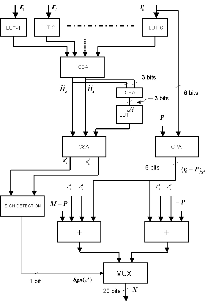 Figure 2: The implemented architecture
|
5 Conclusions
In this paper a general algorithm for N moduli CRT based
conversion is presented. Starting from this formulation a
fast architecture has been obtained. This architecture is
able to perform the conversion by using general moduli sets
including a power of two module. The architecture has been
implemented by using carry save adders and has
been mapped on a FPGA. The obtained results indicate that
LUT based FPGAs can be an effectively used to map RNS
converters architectures.
Appendix A
The range of e is
Moreover, the term [H\tilde] is bounded by
|
|
~
H
|
-
|
= -2k+1 Ł |
~
H
|
< |
~
H
|
+
|
= N · |
~
M
|
|
| (A.2) |
From
A.1 we have
Substituting [H\tilde]+ respectively in
the left side and [H\tilde]- in the right side of A.3 we obtain
Consequently the range of a is -2k < a < N
References
- [1]
- M. Bhardwaj and A. Balaram, "Low Power Signal Processing Architectures Using Residue
Arithmetic," Proceedings of IEEE International Conference
on Acoustic, Speech and Signal Processing (ASSP'98), vol.
5, pp. 3017-3020, 1998.
- [2]
- G. C. Cardarilli, A. Nannarelli and Marco Re, "Reducing Power Dissipation in FIR Filters using the Residue
Number System," Midwest Symposium on Circuit and Systems
2000, Lansing, Michigan, Augut 8-11, 2000.
- [3]
- R. Conway, J. Nelson, "Fast Converter for 3 Moduli RNS Using New Property of CRT," IEEE Trans.
on Computers, Vol. 48, no. 8, pp. 852-860, August 1999.
- [4]
- D. Gallaher, F. E. Petry, and P. Srinivasan, " The Digit Parallel Method for Fast RNS to Weighted Number
System Conversion for Specific Moduli (2k-1, 2k, 2k+1," IEEE Trans. Circuits Syst.-II, Vol. 44, no. 1, pp.
53-57, January 1997.
- [5]
- S. K. Mitra, J. F. Kaiser,"Handbook for Digital Signal Processing," Chapter 9, pp. 611-677, John Wiley & Sons.
- [6]
- S. Piestrak, Ä High-Speed Realization of a
Residue to Binary Number System Converter," IEEE Trans.
Circuits Syst.-II, Vol. 42, no. 10, pp. 661-663, October
1995.
- [7]
- A. B. Premkumar, Än RNS to Binary Converter in 2n-1, 2n, 2n+1 Moduli
Set," IEEE Trans. Circuits Syst.-II, Vol. 39, no. 7, pp. 480-482, July 1992.
- [8]
- A. B. Premkumar, M. Bhardwaj, and T. Srikathan, "High-Speed and Low-Cost Reverse Converters for the
2n-1, 2n, 2n+1 Moduli Set," IEEE Trans. Circuits
Syst.-II, Vol. 45, no. 7, pp. 903-908, July 1998.
- [9]
- K.M. Elleyth, M.A. Bayoumi, "Fast and Flexible Architectures for
RNS Arithmetic Decoding," IEEE Trans.Circuits Systems.-II Analog and
Digital Signal Processing, Vol.39, No.4, pp. 226-235, April 1992.
- [10]
- F. Barsi, "Mod m arithmetic in binary systems," Information Processing Letters,
Vol.40, No.6, pp. 303-309, 30 December 1991.
- [11]
- W.L.Freking, K.K.Parhi, "Low-Power Digital Filters Using Residue
Arithmetic," Thirthy-First Asilomar Conference on Signals,
Systems and Computers 1998, Vol. 1, pp.739-743, 1998.
- [12]
- G.Cardarilli, M. Re, R.Lojacono, " A Residue to Binary Conversion Algorithm for Signed Numbers,"
European Conference on Circuit Theory and Design ECCTD '97,
Vol. 3, pp. 1456-1459, 31 August - 3 September 1997,
Budapest, Hungary.
- [13]
- N.S. Szabo and R.I. Tanaka, "Residue Arithmetic and its Applications in Computer Technology," New York:
McGraw-Hill, 1967.
- [14]
- M.A. Sodestrand, W.K. Jenkins, G. A. Jullien, F. J. Taylor, "Residue Number System Arithmetic: Modern Applications in Digital Signal Processing," New York: IEEE Press, 1986.
File translated from
TEX
by
TTH,
version 2.70.
On 5 Nov 2001, 15:26.