Electronic Appendix to "Imprecise Arithmetic for Low Power Image Processing"

Presented at 46th Asilomar Conference on Signals, Systems, and Computers. Pacific Grove (CA), USA. Nov. 2012.


From article in proceedings:

4.2  Inverse Discrete Cosine Transformation (IDCT)

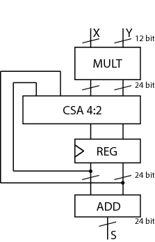
Now we combine the imprecise multiplier schemes with an error-free adder in a multiply-add (and accumulate) unit (Fig. 10) which can be used for the trivial implementation of the Inverse Discrete Cosine Transform (IDCT), which is part of the JPEG decompression algorithm.

For the unit of Fig. 10 we opted for carry-save (error-free) accumulation to keep separate the imprecision due to the multiplier and to the adder. Based on the results of software simulations, we decided not to use a sloppy adder as the extra error introduced was negligible.

We implemented the multiply unit of Fig. 10 with several variants of imprecise multipliers. Based on Fig. 8, we excluded from the IDCT evaluation radix-2 truncated multipliers (more power hungry than all others) and the sloppy-columns schemes (power dissipation savings are marginal when the error increases). In summary, we implemented the following multiply-accumulate units:

Figure 10: Scheme of multiply-accumulate used for IDCT.

  1. r4-mult: radix-4 12×12-bit multiplier and 24-bit adder;
  2. r4-trunc-6: r4-mult with t = 6 truncated bits and 18-bit CSA 4:2, registers and adder;
  3. r4-trunc-8: r4-mult with t = 8 truncated bits and 16-bit CSA 4:2, registers and adder;
  4. sloppy-row-2: radix-4 multiplier with k = 2 sloppy rows and 24-bit adder;
  5. sloppy-row-3: radix-4 multiplier with k = 2 sloppy rows and 24-bit adder;

The complete visual results of the IDCT test are reported below.

The results in Table V are obtained by implementation in a 90 nm standard cells library (clock rate is 100 MHz). The errors are computed with respect to a floating-point software implementation (quantization error for r4-mult).

Unit delay area uma huse power ratio
MULT [ps] [μm2] Pave [μW] eave emax Pave [μW] eave emax  
r4-mult 1398 7702 208 3.7 9 284 3.8 10 1.00
r4-trunc-6 1254 5778 163 5.1 22 224 8.1 24 0.78
r4-trunc-8 1244 5197 143 24.2 115 194 42.9 129 0.68
sloppy-row-2 1286 7003 189 4.2 40 255 5.1 47 0.90
sloppy-row-3 1286 6839 180 11.3 157 239 14.7 189 0.85

Table 5: Summary of result for IDCT implementation.

The results show that the larger reduction in power is obtained for radix-4 truncated multipliers. This is in large part justified by the smaller area required by the accumulate circuitry (accumulate-path: CSA 4:2, two registers and final adder) that for the truncated schemes are reduced up to 33% (16 vs. 24 bit accumulate-path). For the multiplier itself, as shown in Fig. 8, the smaller sloppy rows in the sloppy scheme compensate for the larger tree when compared to the truncated multipliers.

The complete visual results of the IDCT test are reported below.


Visual Results

Error map computed as the absolute value of the difference between the floating-point Ifp and sloppy Isl value of intensity (luminosity) per pixel (i,j):
εi,j = | Iefi,j - Isli,j |
Histogram drawn by taking
εi,j = Iefi,j - Isli,j
(not the absolute value)

r4-mult

Decompressed Image

Error Map

Error Histogram

Decompressed Image

Error Map

Error Histogram


r4-trunc-6

Decompressed Image

Error Map

Error Histogram

Decompressed Image

Error Map

Error Histogram


sloppy-row-2

Decompressed Image

Error Map

Error Histogram

Decompressed Image

Error Map

Error Histogram


r4-trunc-8

Decompressed Image

Error Map

Error Histogram

Decompressed Image

Error Map

Error Histogram


sloppy-row-3

Decompressed Image

Error Map

Error Histogram

Decompressed Image

Error Map

Error Histogram


Alberto Nannarelli